Request to Customer Support
Incorrect nickname or password
Fill all fields
Captcha error
Error
R (Resistor), C (Capacitor), L (Inductor), U (IC), J (Connector) ANT3100 / ANT3101 / ANT3300 Professional Micro-Soldering Repair Guidelines
The board is designed to interface directly with low-power RISC-V SoCs, providing high computational power for industrial IoT.
A single central motherboard cannot fit every physical button, charging socket, or microphone array. The addresses this space limitation by acting as a master control unit that routes peripheral interfaces through flexible printed circuits:
In essence, the C3E-MB-PCB-V4 is a designed for low-power, high-reliability embedded systems. It typically features a SoC (System on Chip) architecture, soldered RAM options, and extended temperature tolerances.
The C3E-MB-PCB-V4 stands at the forefront of PCB technology, offering a combination of high-speed performance, compact design, and reliability that is unmatched in the industry. Its applications span a wide range of sectors, from computing and communication to automotive and medical technology. As the electronics industry continues to evolve, the C3E-MB-PCB-V4 is set to play a crucial role in enabling the development of more advanced, efficient, and capable devices. With its advanced features and the impact it is poised to make, the C3E-MB-PCB-V4 is a testament to the power of innovation in meeting the challenges of the future.
: Document archives hosted on Scribd's C3E Document Repository provide detailed layout bitmaps used for identifying hidden trace connections.
To make sure you're getting the right technical help, can you tell me:
This article provides a comprehensive overview of the C3E-MB-PCB-V4, its functionalities, technical aspects, and its role in industrial automation and automotive diagnostics. 1. What is the C3E-MB-PCB-V4?
The SPI flash layout and EC firmware are entirely different. Doing so will brick the mainboard.
PWR: 12-24V DC J1: ETH0 J2: ETH1 J3: USB-D DEBUG: UART1
If you are working on a specific repair or hardware project, please let me know: What is the board currently presenting?
You will often see multiple small relays on the board. These are responsible for switching between different communication pins on the vehicle's OBD-II diagnostic port.
Micro-soldering adjustments on this platform require strict adherence to multi-layer thermal profiles, as inner-layer copper pours disperse heat rapidly across the board chassis.
: Use a preheater set between 100°C and 120°C before applying hot air to pull shield cans ( SH402 ). This lowers the risk of board warping or internal layer separation.
The prefix most likely denotes the project code or product family. In engineering nomenclature, such prefixes anchor the board to a specific ecosystem or system-on-module (SoM). The "c" could signify a "C-series" processor family (e.g., from Espressif, NXP, or a custom ASIC), while "3e" might indicate a variant with enhanced Ethernet, EEPROM, or energy-efficient features. Alternatively, "c3e" could refer to a specific customer or contract designation—e.g., "Customer 3, Engineering revision E." Regardless of the exact decoding, this segment provides the high-level context: this PCB does not exist in isolation but as part of a larger embedded system, likely for industrial control, consumer IoT, or automotive telematics.
Probe test points flanking the display connector interfaces for digital signal consistency.
In the rapidly evolving world of embedded electronics, nomenclature often tells a story. Part numbers like are not random strings of characters; they are blueprints of functionality, revision history, and engineering intent. For procurement specialists, embedded systems engineers, and hardware hobbyists tackling next-generation industrial control, understanding the nuances of the C3E-MB-PCB-V4 is crucial.
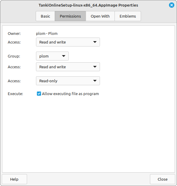
In order to make the game work, enable the «Allow executing file as program» in the app's properties.